![]()
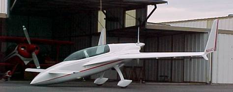
Starting at the Nose, details of the aircraft are described:
1.) Extended nose: The nose has been extended 7 further forward than plans. This gives the plane a Long look and avoids the somewhat short blunted appearance of the noses of some VEs. Extending the nose required photographic enlargement of the forward-most bulkhead (forward of the battery) and several other changes that allowed aft geometry to fair in. Bulkhead F-22 was not changed. The nose extension was not a mere matter of microing on a few additional blocks of foam, and in fact impacted the fairing of the outer top sides and belly skins back to the forward canopy area. Many favorable comments have been received regarding the contouring of the forward fuselage area. Through extending the nose, slightly less epoxy / lead shot ballast was required forward of the forward-most bulkhead for CG purposes: only 6 pounds. With the nose gear extended, the airplane will comfortably stand on all 3 wheels, with about 8 pounds on the nose wheel. There is little worry of it flipping over backwards as with some EZs.
2.) Battery Box: The battery box was formed from ¼ birch aircraft plywood with internal flox corners and 2-ply BID internal lay-up. Its forward and bottom sides are reinforced with a 4130 chromoly steel plate floxed in place with a 2-ply external lay-up was made over all. A ¼ stud is welded to the bottom steel sheet which extends through the structure of the forward retract area. A nut is accessed from inside the nose strut trough from below. The forward portion of the steel sheet attaches via 2, dash 3 fasteners to the aft face of the forward-most bulkhead into internal nut plates located on the forward side of that bulkhead. Two threaded studs on the left and right sides of the box extend upward to hold down an aluminum retaining bar that spans the top cover of the battery box and securely holds the cover down and closed. The box is intended to contain a battery explosion and generally contain the battery in the event of accident. It is not nearly as heavy as it sounds, and the forward nose area is the only place where slight extra weight is somewhat tolerated. There is a solid-state power supply mounted on the inside skin adjacent to the battery that provides 5 volts DC for small items and circuits that utilize that kind of current.
A sealed Harley battery is currently installed. The battery, as well as the entire nose rudder pedal area is accessible through a separate removable hatch of maximum permissible size allowing the forward area to accessed for rudder pedal and elevator control inspection, battery maintenance and so on without having to remove the canard. Canard attach bolts are oriented facing forward instead of aft and are accessed through this nose cover hatch.
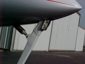
3.) Nose skid: The nose skid is mounted on a .125, polished 316 stainless plate that is held in place by the 2 upper bolts of the nose strut pivot casting. It extends down the strut about 6 inches but is formed to stand clear of the epoxy / glass gear leg. A lower tab of this plate is bonded to the nose strut with flox and wrapped with Kevlar roving. Two approx. 4-inch-long hardened D-2 tool steel Ls capture a hard durometer rectangular strip of ½ inch thick rubber, which is the high-friction, ground-contacting point. The tool steel parts are chrome-plated for corrosion resistance and thermally isolated from the stainless plate through fiberfax ceramic felt. The design intent is this: as with similar aviation axioms: all EZ pilots fall into 2 groups: those that have landed with the nose gear up, and those that will. Typically, the real damage from such events results from intense heat soak into the structure during nose gear-up landing rollout. If such a landing happens, the hard tool-steel skids will take the loads without annealing and being ground away. The ceramic paper and the air gap between the plate and leg will greatly reduce any destructive heat flow into the composite structure.
The hard rubber skid provides a soft dampening when setting the nose down, and good friction. During start-up with the nose down, the plane will not start creeping forward until the throttle is advanced past about 1/3 power.