![]()
4.) Shimmy dampener and nose wheel pant, and nose wheel bearings: An early Rutan Newsletter Mandatory Ground required that the .093-wall 4130 tubing pressed into the cast aluminum nose wheel fork casting be replaced with .125 (min.) wall tubing because some early problems of explosively divergent nose wheel shimmy were encountered by some when the .093 tubing bent slightly. Slight bending negated the original, per plans shimmy dampening system. To solve all of this, a slightly longer .125 wall 4130N tube was pressed into the nose fork casting. A steel part was turned that cross-bolts into the top of the .125 tube. It has a round land and an upwardly extending stud. The stud passes through and captures a horizontally positioned canvas phenolic tongue attached via a small aluminum flange to the lower gear leg. The flange is held in place via flox /Kevlar roving. The stud accepts a short alternatingly stacked set of stainless Bellville (cupped) washers that are compressed by an MS21042-4 nut on the stud. The stack of Bellville washers creates a compressive load on the phenolic tongue and thus a smooth but positive rotational friction. Not only has this unique approach to a nose wheel shimmy dampener worked perfectly, it has required no adjustment or maintenance whatsoever to maintain the required 3 to 4 pound side load pressure test to caster the nose wheel.
By closing off the top of the tube as described above, it then made it possible to similarly seal the bottom of the tube and install a grease zert to pressurize the tube ID with grease. With a small hole drilled through the tube at a level corresponding to the gap between the top and bottom bushings pressed into the nose fork casting, a grease gun is pumped until a little grease is extruded from the bushings. Such means of grease lubrication has resulted in no evident play or wear in the nose fork pivot bushings for 1200+ hours of operation.
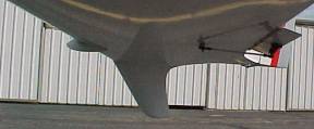
A tightly fitting wheel pant fender, formed from buck-riveted 2024 T351 sheet is attached through the axle bolts, and attached to the top of the fork casting via a 4130 flange. A 4130 strap runs from the axle bolt, around the bottom of the fender to take all of the abuse and various stresses such a wheel pant encounters in operation. The wheel pant has not deteriorated in any way. Its function is to greatly reduce fine gravel abrasion to the prop on take-off. The wheel pant is zinc chromated and white enameled. As for all such assemblies throughout the AC, the original CAD-produced templates and CAD drawings exist if the fender ever needs to be repaired or replaced. All 4130 parts associated with the nose wheel fender were chrome plated for ultimate corrosion resistance, hydrogen embitterment having been considered but deemed (and proven over time) to not be a factor.
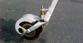
Another problem encountered by a few early VE builders was that when the nose wheel axle bolt is tightened enough to properly adjust the tapered nose wheel bearings, the aluminum bearing bosses riding on that axle bolt would tend to turn on that bolt rather than the bearings turning in the wheel. To correct this on 86EZ, 2 small aluminum spacers are located on the axle bolt, inside the wheel, centered between the 2 bearings. The spacers are machined slightly under-length and final bearing in-out tightness was set by trial assembly and re-assembly, placing gauge shims between the spacers. Once set, this allows the main nose wheel axle bolt to be tightened to full, normal torque specification without effecting bearing tightness. This holds everything nicely together in compression, and the wheel turns only on the bearings, not the axle bolt. To accomplish this condition, the inward-facing surfaces of the fork around the axle bolt holes were precisely spot-faced to hold the bearing bosses true. In general, the entire lower end of the nose strut is more highly developed than the rather simple approaches described in the plans.
5.) Nose wheel blister. The standard nose wheel blister has been modified so that instead of being generally bulbous in shape, it has a flattened top surface. This allows that top surface to better serve for mounting equipment, and such. Currently, the cabin lighting dimmer / power supply is mounted there and in the past, a quartz / infrared electric cabin heat unit has been mounted in this location. The electric cabin heater was subsequently removed and sold, but it works well when the 60-amp Cessna alternator (included) is installed. The ragged current surge as it cycled on and off however eventually damaged the Terra electronic course deviation (ECDI) indicator display and the heater surges were hard on the electronics in general. The blower motor was unshielded, which created RF noise through the radio and noise through the electrical system. A surge suppressor / capacitor and a shielding of certain components of the heater could have solved those problems, and a similar infrared quartz heater could be installed. In any event, there are dedicated high-current circuit breaker-controlled terminals rated at 40 amps on top of the nose wheel blister, and mounting hard points for an infra-red heater, should an electrically shielded and surge protected quartz heater be installed in the future.
6.) Nose retract: the torque tube going from the retract crank handle to the nose retract worm gear incorporates 2 small, machined aluminum faces with a milled annular groove. If the 2, #6 screws are loosened, it allows the crank to be clocked so that it is always at the six 0-clock position when full up or full down. This is to accommodate normal wear of the thrust bushings in the worm gear and keep the crank symmetrical with the panel and out of the way. The shaft passes through the instrument panel in a self-lubricating molybdenum disulphide reinforced nylon bushing, rather than the little green polyethylene standard bushing. Aft of that, the handle itself is bolted to a small precision-machined 2024 T351 aluminum part that functions as a miniature disk brake. A small, second knob locks or unlocks the disk with thumb and forefinger turning. This allows easy and very positive, one-handed unlocking, cranking, and relocking of the nose gear. It will not slip and allow the nose gear to hang out a few inches in flight or slip and hang down in the hangar when being moved. A machined aluminum knob with 2 sets of pressed-in sealed ball bearings in the main cranking knob all combine for a very trouble-free, smooth, light and functional nose gear cranking mechanism.
7.) Roll Trim: The plane has an excellent electric servo roll trim but it is augmented by a bungee type roll trim located at the forward end of the main control system torque tube. It is another small precision-machined mechanism with a sealed ball bearing. It is located under the top surface of the right console just aft of the instrument panel. It is based on a very stiff press-tool-quality tension spring about 2 in length. A small knob passes up through the right console that adjusts the center of the bungee force. It is not meant to be a fine-tuning roll trim that would be adjusted frequently in flight. Instead, it provides a moderate stick centering force. The effect of this is to provide a desirable general centering force on the stick in roll that definitely crates a slightly more solid feel to the stick, more in harmony with the pitch. In actuality, once the neutral center point is set, it is almost never changed.
The electric trim is based on a retract servo used in RC model planes. Retract servos are used to retract landing gears on large RC models and thus have one additional level of reduction gearing. Compared to the fast-acting servos, they move much slower, and generate much higher torque. The servo tab on the right wing is activated by such a servo, which in turn is activated by a small centering momentary contact rocker switch just forward of the control stick. All I can say is that it works just right with more authority than is ever needed, and due to its slow response, it can be fine-tuned to hold the nose absolutely still in heading. I will crank it to one extreme to do a roll in that direction, but otherwise it stays within a few degrees of roll neutral in level flight.