![]()
8. Consoles and console-mounted controls: According to Burt Rutan, the cockpit consoles are structural and contribute to the stiffness of the fuselage. Once glassed in, they unfortunately make it impossible to access many flight-critical mechanisms such as the control system on the right side and the belly board (air brake) actuation and pitch trim assemblies on the left. To counter that problem, removable access panels are installed.
The belly board pulley, cables and actuator pivot gave a lot of builders problems, and many of the belly boards actuators suffered from alignment problems and they cables could not be kept straight and very tight. To solve this, an aluminum hard point was installed on the console to handle the surprisingly high forces generated when extending the airbrake. Also, small turnbuckles were installed in the actuator cables so their tension could be adjusted, which also allows desirable, exact positioning of the belly board airbrake handle when the airbrake is in the closed position.
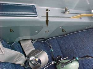
above:
a. airbrake lever pivot hard point
b. typical removable access panels
9. Instrument panel: The canopy latch, according to plans, extends perpendicularly aft from the instrument panel. By angling the canopy latch downward from a higher attach point on the panel; it was possible to place six, 3 1/8 instruments across the width of the panel. (The radios are 3 1/8 wide) Below is a picture of the panel. Below that is a description of the instruments.
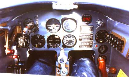
At the lowest right corner of the panel, partially hidden by the stick is a 2 ¼ recording G-meter.
Directly above that is a dual gauge. It was a combination that never had been ordered before at that time. The manufacturer made new art to silk-screen the bezel; it is a combination system voltage / carburetor air temp. gauge. The quad gauge above that registers cylinder head temp., exhaust gas temp., oil temp. and oil pressure. The oil pressure section of the quad gauge is de-activated in favor of the larger red LED oil pressure gauge to the left of the magneto switch.
Below and to the left of the quad gauge is a red push button switch. It is an aux. push to transmit button in the event that the PTT on the control stick fails.
Below the oil pressure LED gauge is a liquid quartz tachometer display. The exact revs are displayed for 1 second, to be replaced with the exact average revs for the next second and so on. This tachometer requires no system voltage and operates from an eddy current produced by a proximity sensor mounted near the prop. Flange. This tachometer works exceedingly well, and is particularly well suited for leaning at high altitude.
Below the tachometer is the Terra 720 channel single nav/com stack.
Directly to the left of the radios is the VSI, which indicates to 3000 feet per minute rather than 2000 or 6000.
Directly above the VSI is the airspeed indicator, which has green, yellow, and VNE ranges etc. set for this AC.
To the left of the airspeed is an electric turn and bank.
Below that is the electronic course deviation indicator, (ECDI), which displays the output of the nav radio. It uses a gas-discharge display and has a few additional features beyond a standard swinging needle VOR head. The brightness of the display is automatically controlled by a photocell and automatically adjusts itself to the ambient lighting conditions of the cockpit.
To the left of the ECDI is an Edo-Air transponder. It is the aux. transponder from a Lear Jet, and is TSOd to squawk to the radio-horizon at 49,000 feet. It is 300 watts whereas most light aircraft transponders are 100 or 150 watts. It is connected to an encoder mounted forward.
Above the transponder are 3 phone jacks. The lower 2 are for the headset when not plugged into the intercom. The top jack is audio output from the radio so a small speaker can be plugged in to listen to ATIS or traffic during pre-flight.
Directly left of the 3 jacks is a clock.
Below the clock are 3 lights. The left light is steady red and lights when oil pressure drops below 12 pounds. When it comes on, the Hobbs meter goes off. It is activated by a pressure switch located just forward of the firewall. That pressure switch is mounted on an aluminum manifold that also includes the oil pressure sender.
The center light glows steady red and indicates when the warning system is defeated. It will light when the warning horn is defeated and is connected to a relay that enables the warning system to reset itself each time an abnormal flight configuration exists. For example, the horn sounds if the throttle is advanced without the canopy being locked or if the throttle is closed and the nose gear is not down and over center-locked. The right light is yellow and flashes when the fuel transfer switch is on. If you will notice above the 3 jacks there is a switch. It turns off all 3 lights off should any of them light up at night interrupting night vision. The altimeter is at the far left of the panel.
Above the altimeter is the canopy latch bracket. Incorporated within that latch bracket is for / aft adjustment to set the tightness of the 3 canopy latches. Above that is a switch that switches the transponder from mode A to Mode C operation.
Only partially visible in the photo above is the nose gear retract crank. Behind and below it (not shown) is a small, angled sub-panel. It contains the ammeter, master switches, main circuit breaker, and a heavy lighted switch for the electric cabin heater (no electric heat is currently installed).
The panel has one additional ply of BID glass on its aft face for additional stiffness.
The radios and the several other critical instruments are internally lighted for night flight. There are also gimballing black-lites mounted on the underside of the canopy that shine down on the unlit instruments. Eyebrow lights light critical flight instruments, and the whole cockpit can be flooded with a map light mounted on the right side of the roll over structure, near the top.
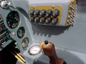
On the right cockpit wall is mounted the switch / fuse panel. Forward of the stick is white OAT gauge. It is an industrial gauge that is accurate, and reads from an alcohol bulb mounted just forward of the nose gear pivot.
The compass is mounted further rearward on the upper right side of the cockpit. The compass is internally lighted and the compass box contains a switch controlling the gimballing black lights that shine down on the instrument panel from the underside of the canopy.
The electrical system has never blown a fuse of tripped a circuit breaker.